
Rubber vibration isolation
Rubber vibration isolation reduces transmission through a resilient support when the isolator is correctly matched to the equipment. Start by identifying the vibration source and the path into the surrounding structure. A loose fixing or an unbalanced component may need correction before a change of support is useful.
Select the isolator using the load at each position, operating frequency, mounting direction and permitted movement. Compare its loaded height with the clearances around the machine. Making a support softer is not automatically an improvement if it allows excessive movement or is poorly matched to the operating conditions.
During installation, keep pipes, cables and restraints from forming unintended rigid paths around the rubber support. Assess the result with the machine operating normally and inspect for settling, damage or loosened attachments during service. Useful selection information includes the equipment mass, mounting layout and the vibration problem to be addressed.
Vibration Mount Size Catalog
Compare five mounting arrangements using the matching drawing, thread and dimensional data. Load and compression columns retain their stated units; confirm operating conditions for your installation.
Vibration Damping Mounts A
Match D, H and thread d to the drawing, including stud length L. Dimensions are in mm; thread designations, load in kg and compression in mm follow the table headings. Confirm load direction and operating conditions for your installation.
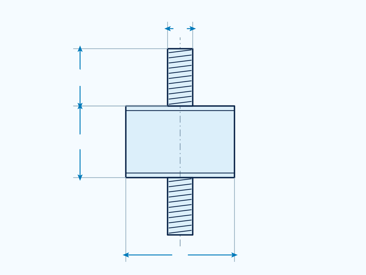
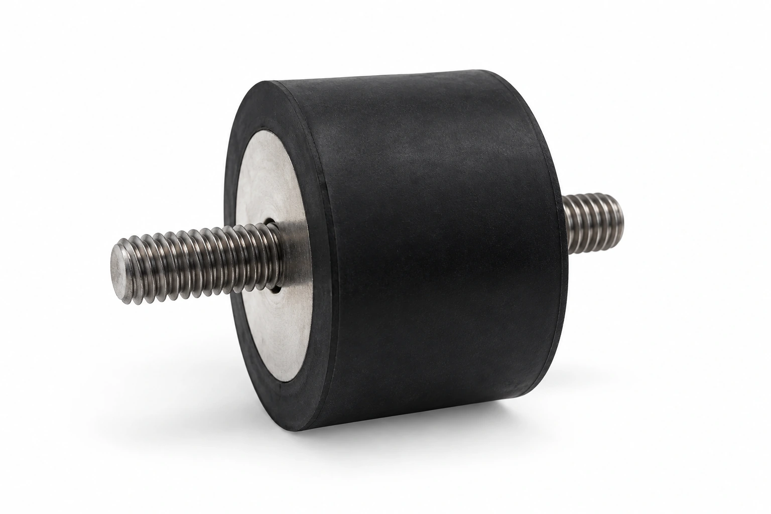
Anti-Vibration Rubber Mounts B
Match D, H and thread d to the drawing, including stud length L. Dimensions are in mm; thread designations, load in kg and compression in mm follow the table headings. Confirm load direction and operating conditions for your installation.
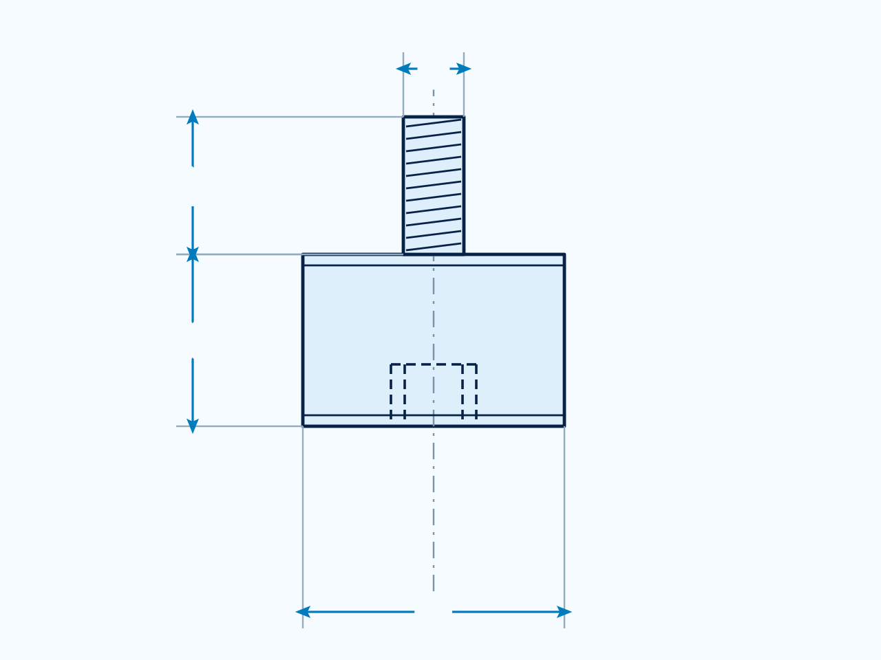
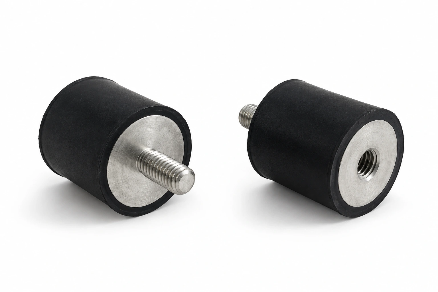
Vibration Isolators C
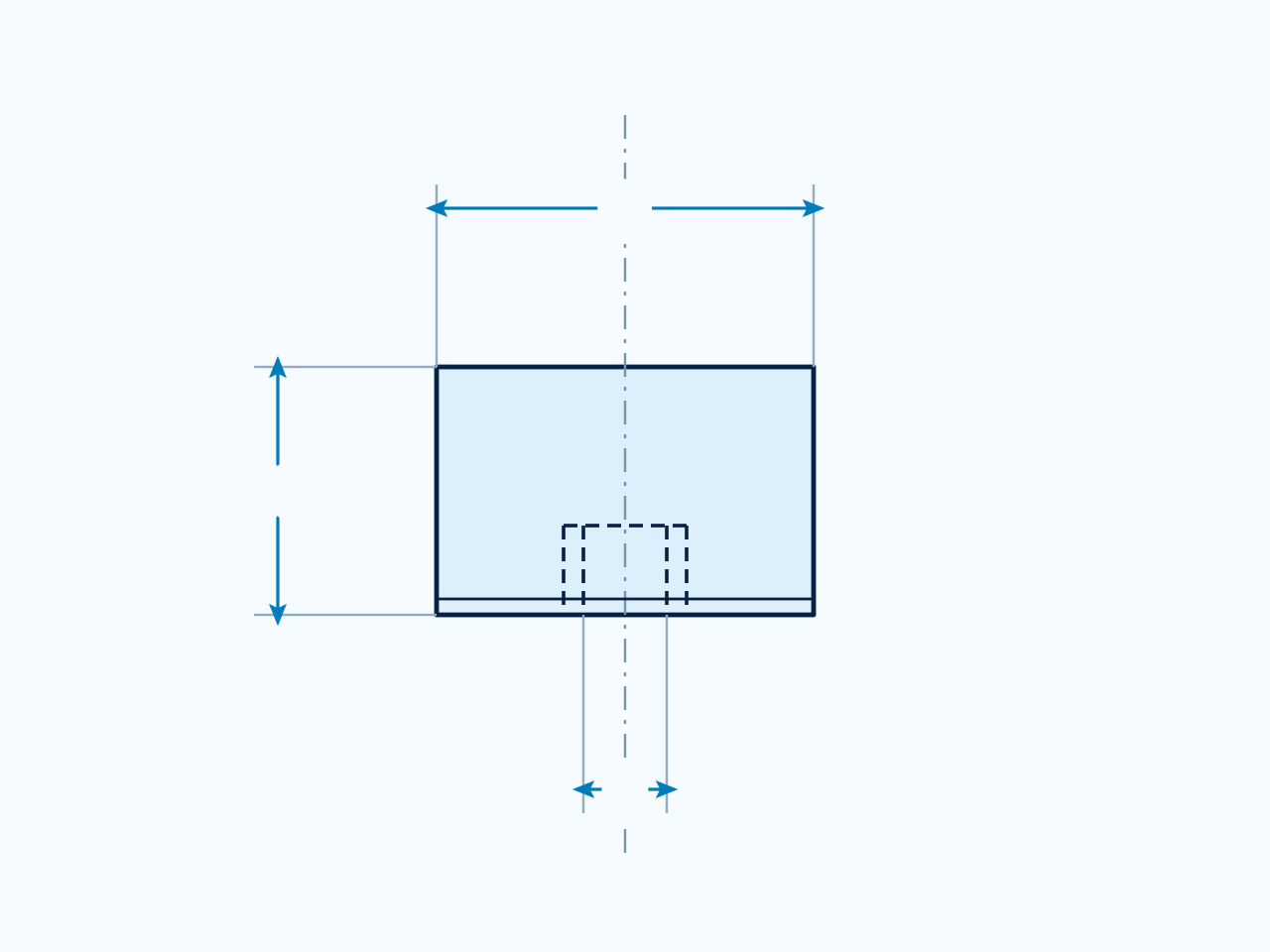
Match D, H and thread d to the drawing. Dimensions are in mm; thread designations, load in kg and compression in mm follow the table headings. Confirm load direction and operating conditions for your installation.
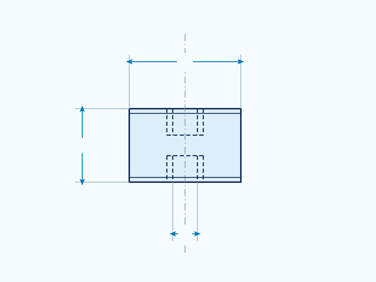
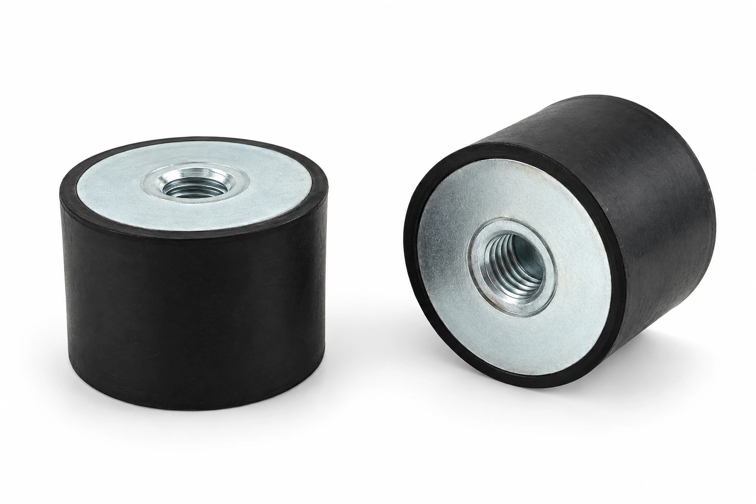
Rubber Mountings D
Match D, H and thread d to the drawing, including stud length L. Dimensions are in mm; thread designations, load in kg and compression in mm follow the table headings. Confirm load direction and operating conditions for your installation.
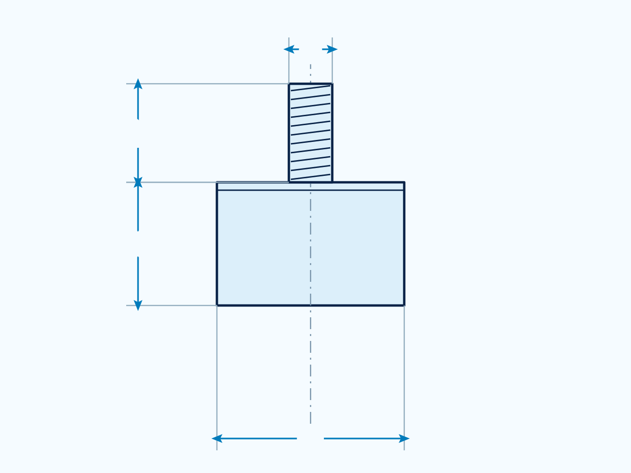
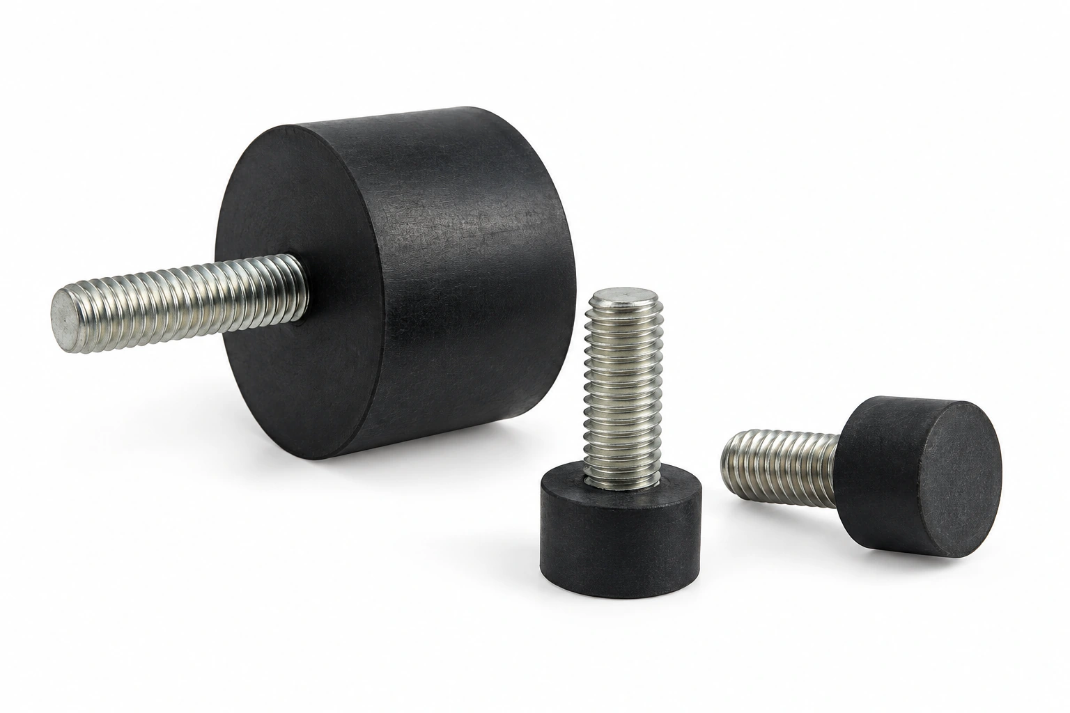
Rubber Vibration Mounts E
Match D, H and thread d to the drawing. Dimensions are in mm; thread designations, load in kg and compression in mm follow the table headings. Confirm load direction and operating conditions for your installation.
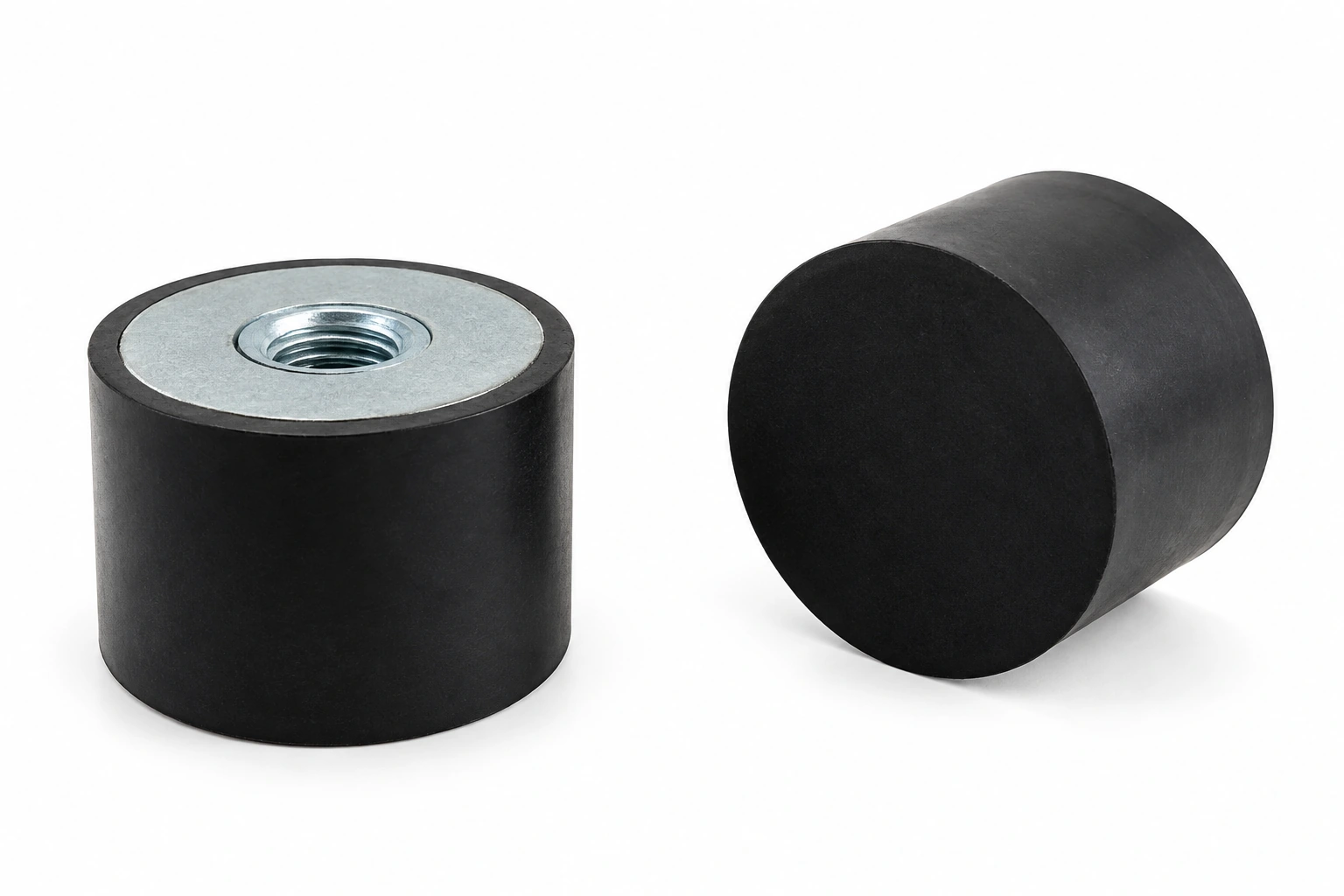
Need a different size? Share your drawing, mating dimensions and intended use to discuss a suitable part.
Discuss Your RequirementsProduct specifications
- Application focus
- Reducing structure-borne vibration through an appropriately matched rubber support.
- Initial assessment
- Identify the source and transmission path, including loose or unbalanced components.
- Selection criteria
- Load per support, operating frequency, direction and permitted movement.
- Bypass prevention
- Review pipes, cables, fixings and restraints around the isolator.
- Service checks
- Assess running behavior, settling, damage and loosened attachments.
Need a quote or a custom part?
Send your requirements, drawings or samples to discuss standard and custom silicone rubber parts.
Email us[email protected]