
Generator Motor Mounts
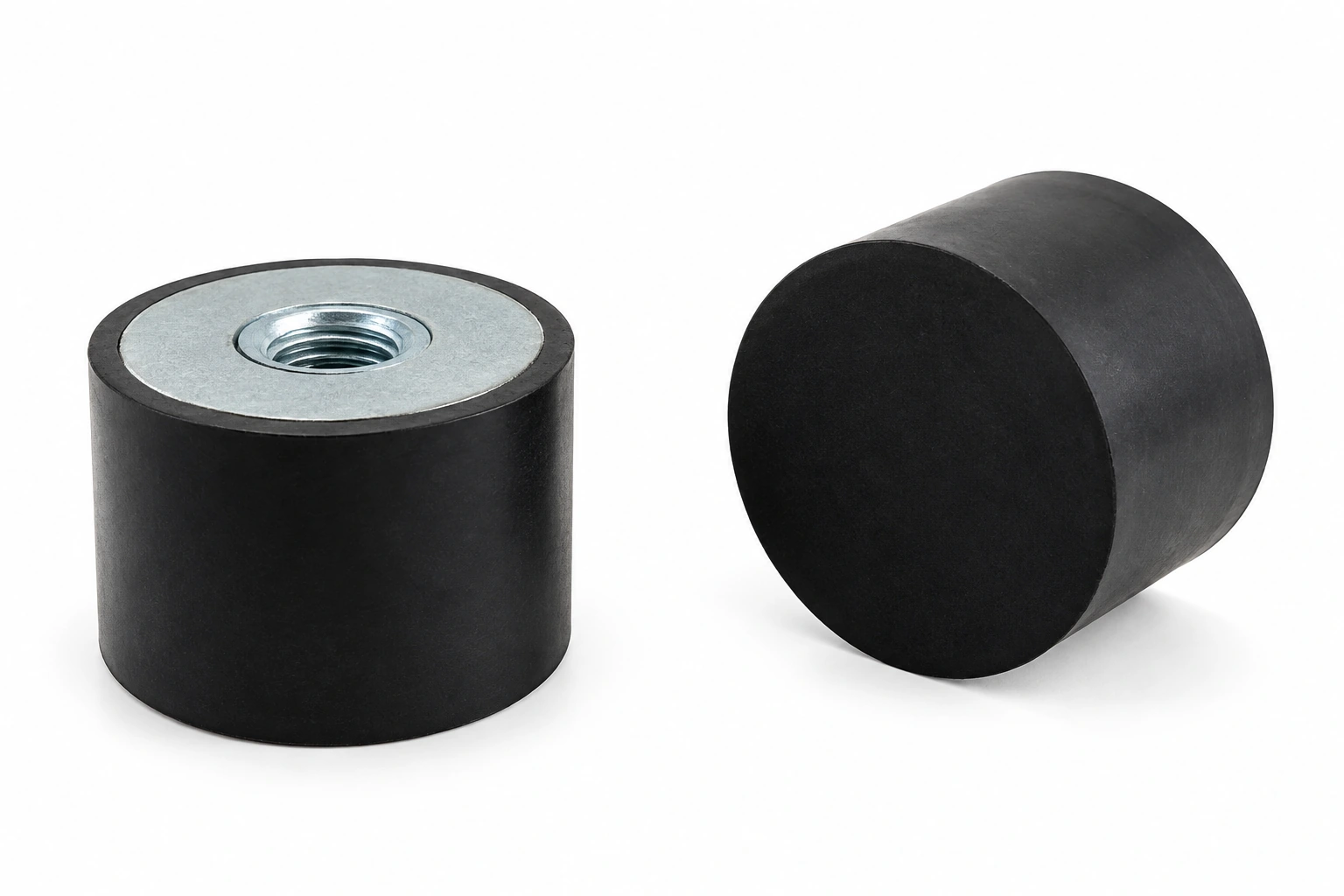
Generator motor mounts support the motor or generator assembly and influence how vibration is transmitted to its frame. Begin with the mass, center of gravity and mounting positions. These determine the load at each mount and the space available for its deflection.
A rubber pad and a rubber-to-metal mount have different attachment requirements. For a mount with studs, inserts or plates, specify thread details, fixing centers and the load direction. Check the installed height and alignment so that the mount is not forced into an unintended sideways load during assembly.
Choose the design for the equipment’s speed range, expected movement and exposure to heat or fluids. No general mount description establishes a percentage reduction in vibration. After installation, assess the supported assembly and inspect both the rubber and its attachments for changes that could affect stability or isolation.
Vibration Mount Size Catalog
Compare five mounting arrangements using the matching drawing, thread and dimensional data. Load and compression columns retain their stated units; confirm operating conditions for your installation.
Vibration Damping Mounts A
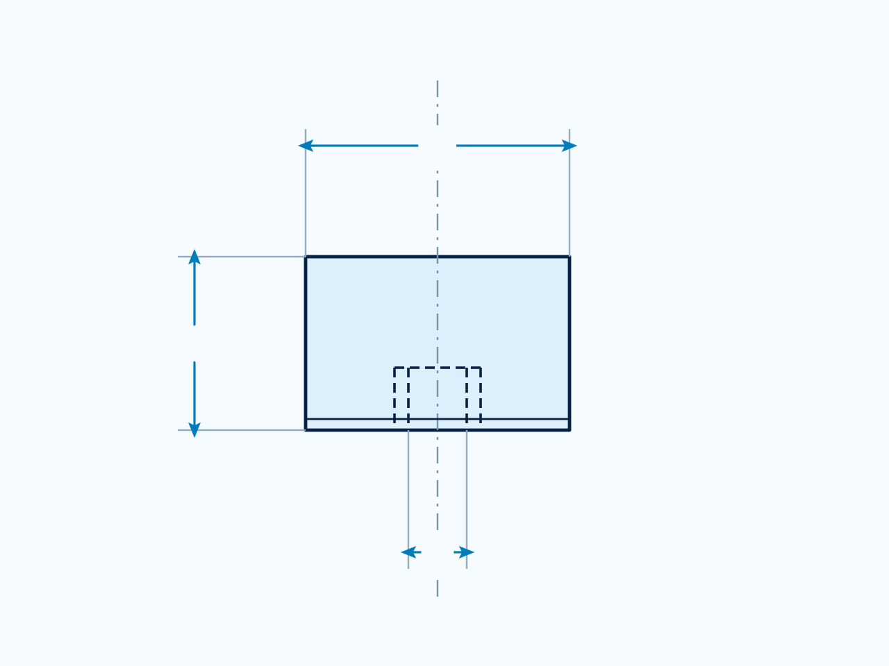
Match D, H and thread d to the drawing, including stud length L. Dimensions are in mm; thread designations, load in kg and compression in mm follow the table headings. Confirm load direction and operating conditions for your installation.
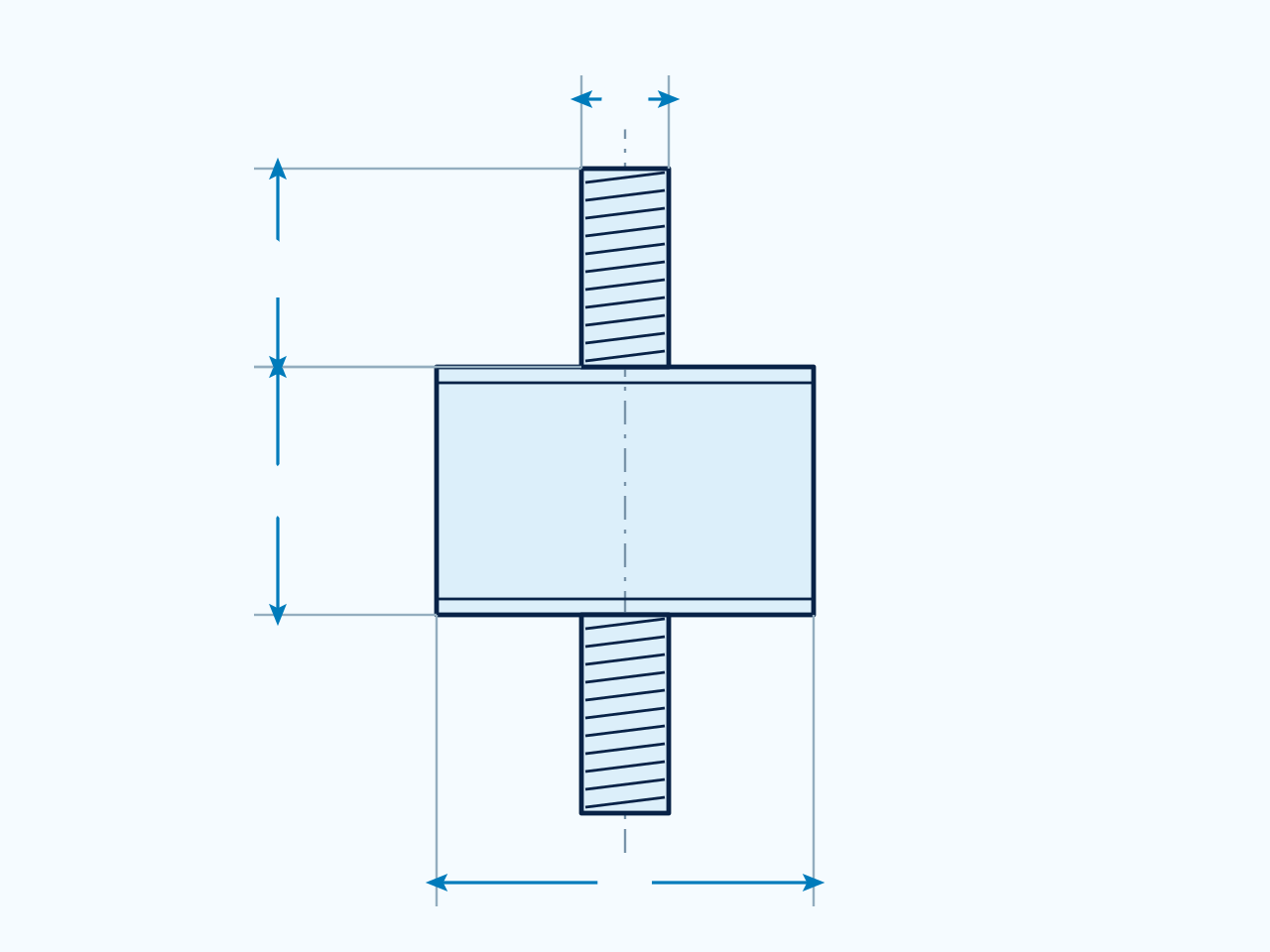
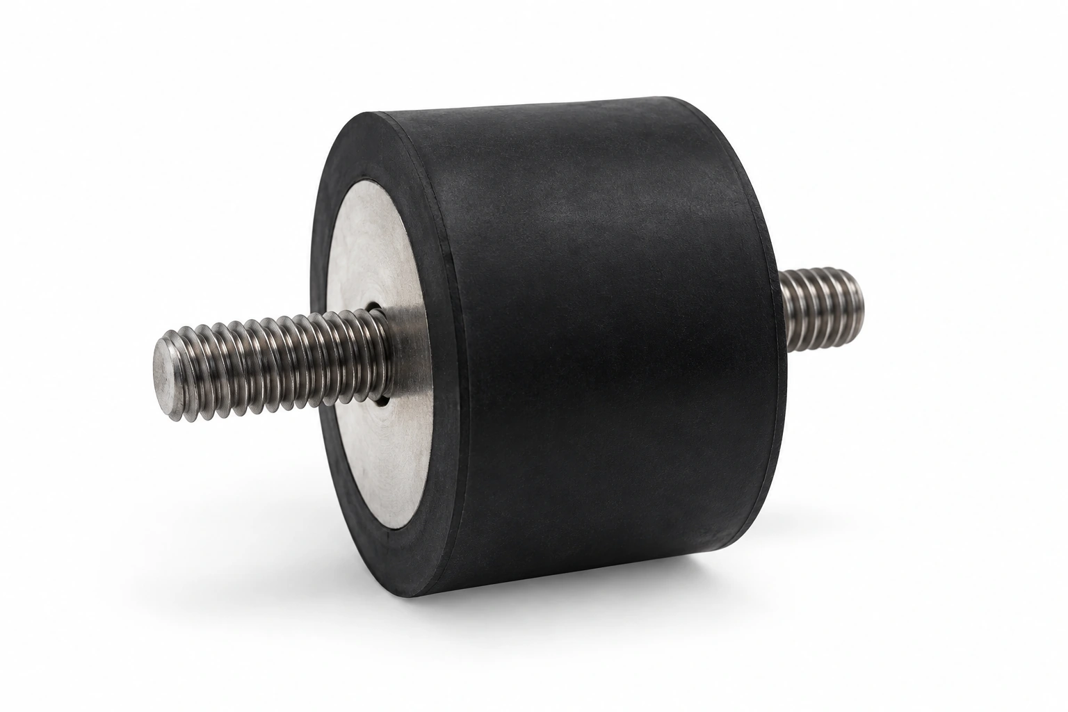
Anti-Vibration Rubber Mounts B
Match D, H and thread d to the drawing, including stud length L. Dimensions are in mm; thread designations, load in kg and compression in mm follow the table headings. Confirm load direction and operating conditions for your installation.
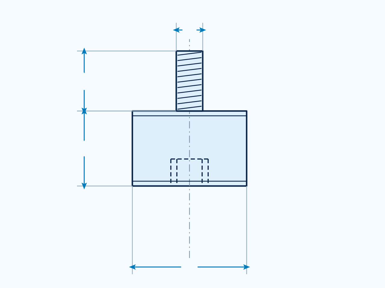
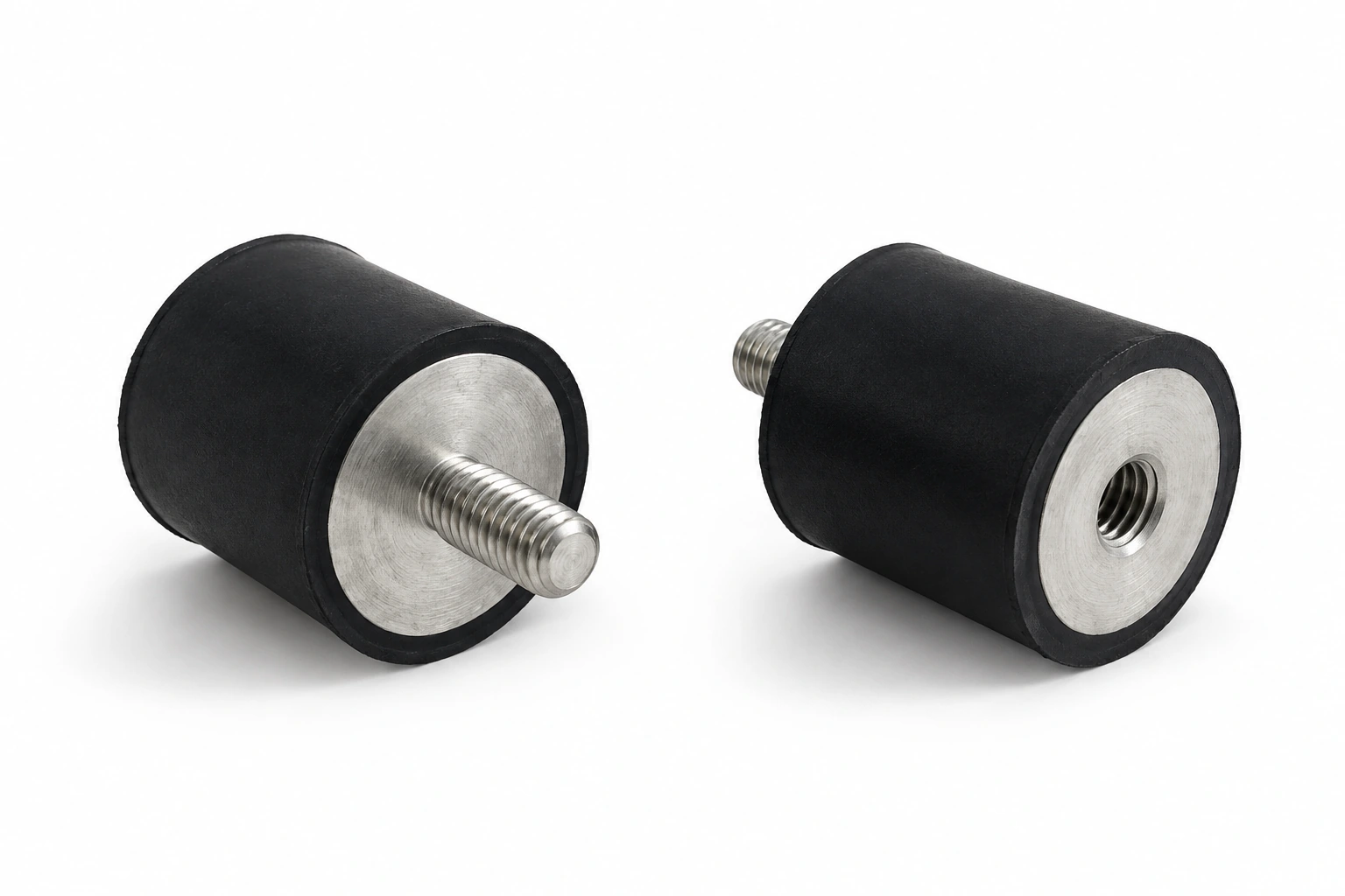
Vibration Isolators C
Match D, H and thread d to the drawing. Dimensions are in mm; thread designations, load in kg and compression in mm follow the table headings. Confirm load direction and operating conditions for your installation.
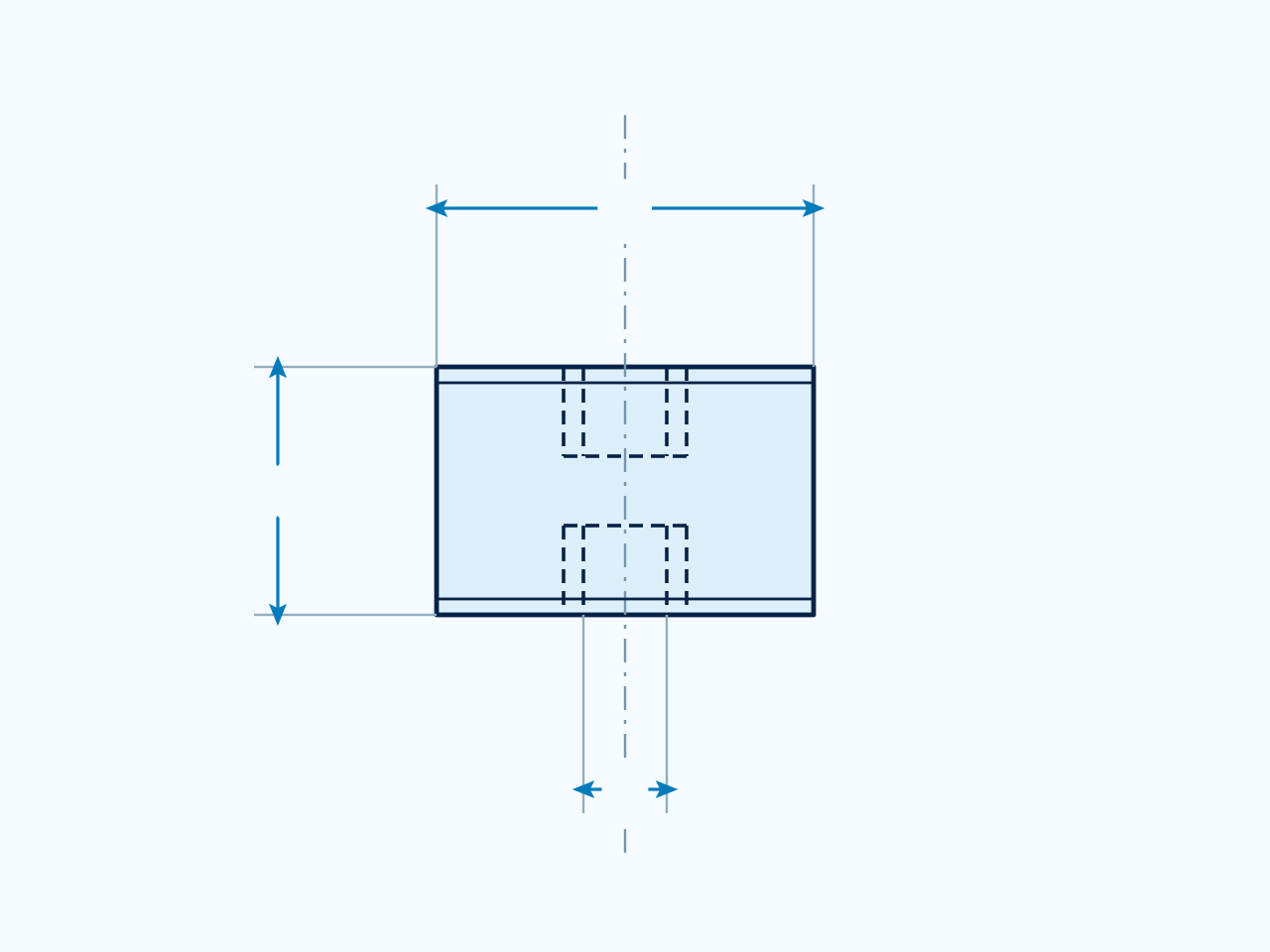
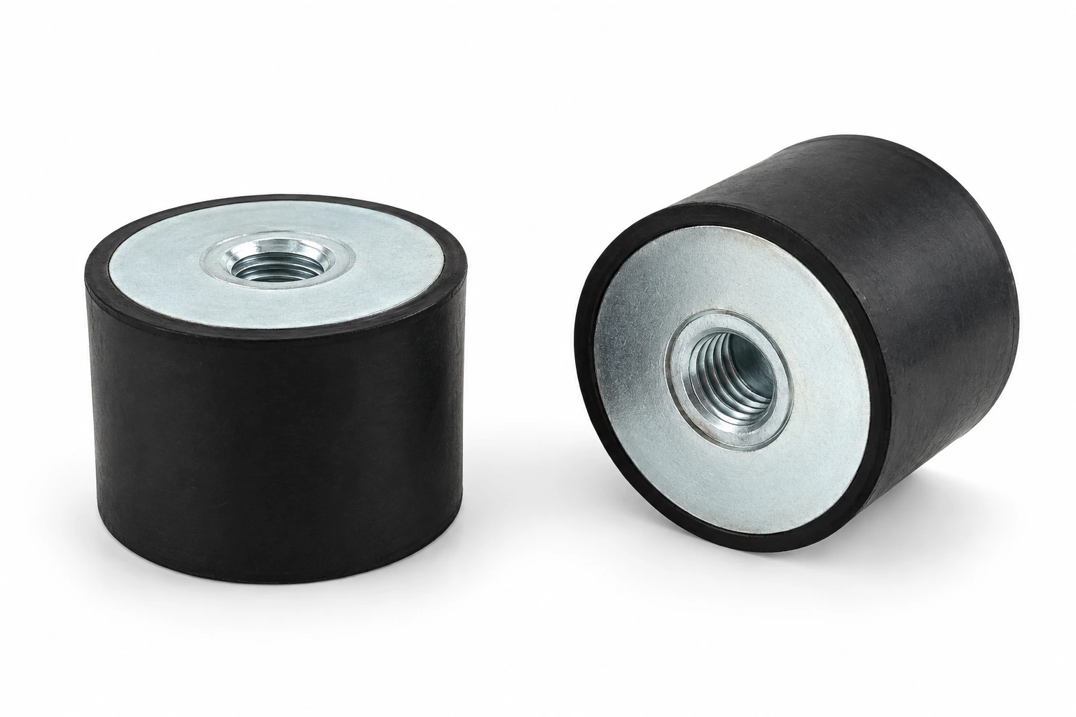
Rubber Mountings D
Match D, H and thread d to the drawing, including stud length L. Dimensions are in mm; thread designations, load in kg and compression in mm follow the table headings. Confirm load direction and operating conditions for your installation.
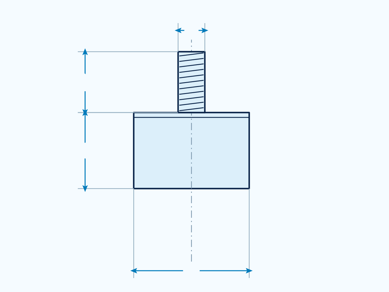
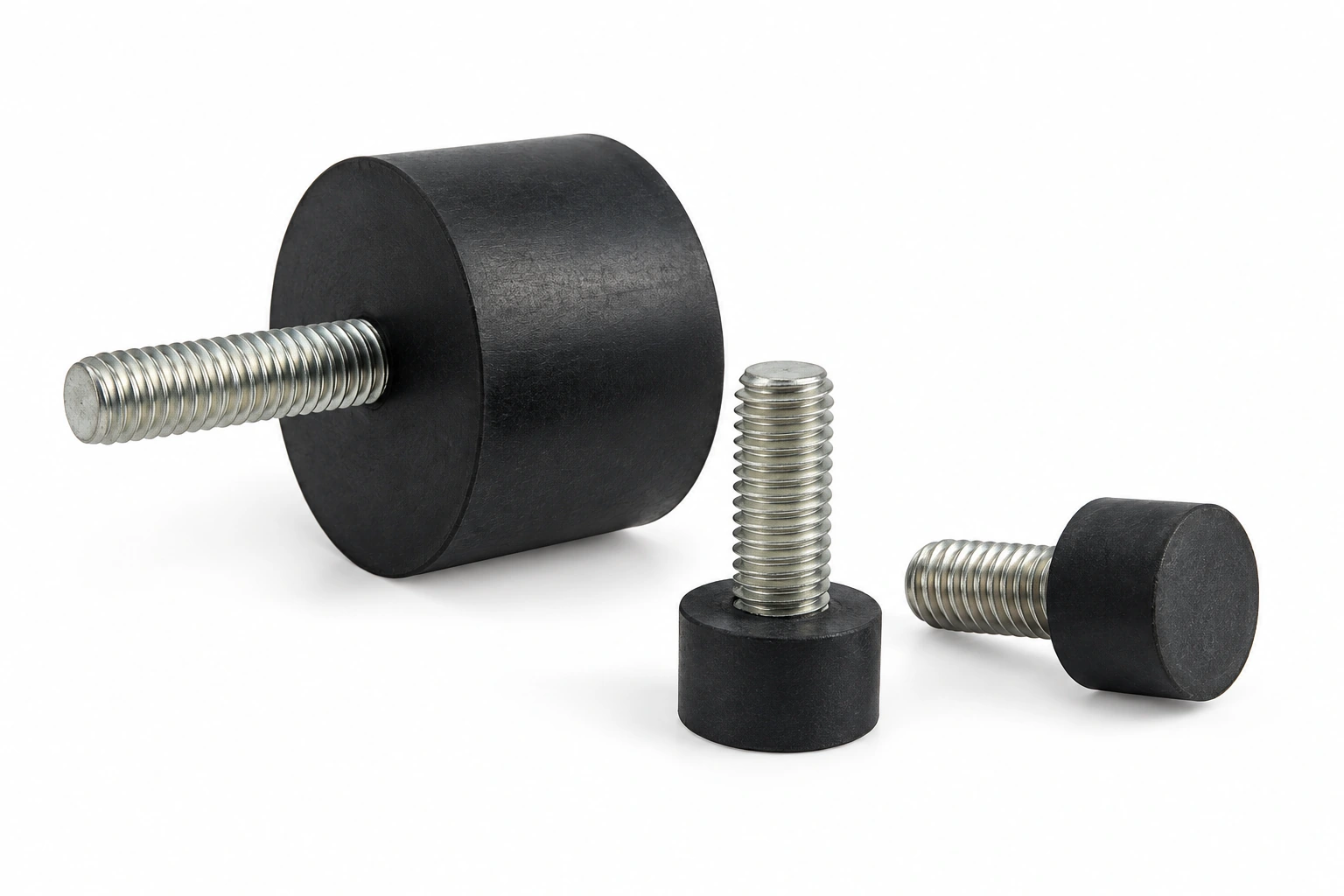
Rubber Vibration Mounts E
Match D, H and thread d to the drawing. Dimensions are in mm; thread designations, load in kg and compression in mm follow the table headings. Confirm load direction and operating conditions for your installation.
Need a different size? Share your drawing, mating dimensions and intended use to discuss a suitable part.
Discuss Your RequirementsProduct specifications
- Product form
- Mount supporting a motor or generator assembly on its frame.
- Load inputs
- Mass, center of gravity and mounting positions.
- Fixing details
- Stud or insert thread, fixing centers and intended load direction.
- Installed geometry
- Check loaded height, alignment and movement clearance.
- Service exposure
- Assess operating speed range, heat, fluids and attachment condition.
Need a quote or a custom part?
Send your requirements, drawings or samples to discuss standard and custom silicone rubber parts.
Email us[email protected]