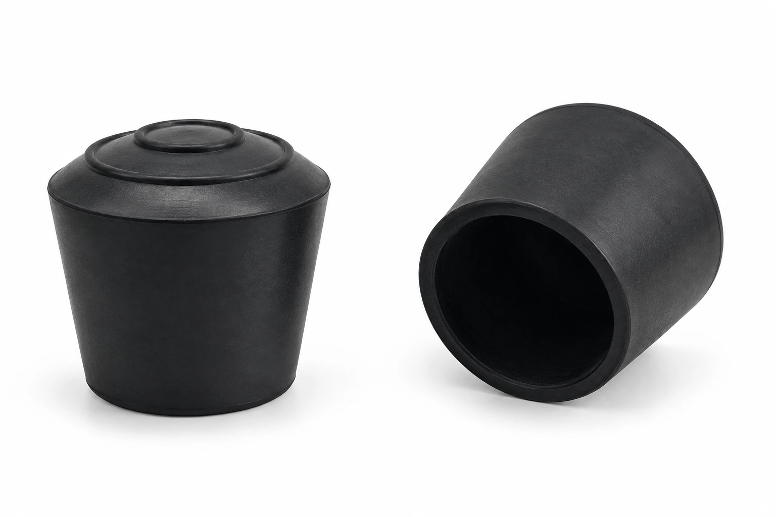
The rubber machine feet are units that are used to protect the machines from any harm, damage, and breaking. These small accessories can be implemented in any production process where the engines produce a lot of vibrations and noise, and they are mounted there to create a safer environment and better process.
When choosing the rubber machine feet, you should pay close attention to several things so that you can avoid any problems or mistakes. You should first figure out the weight of the machine and the exact number of feet that will need to be implemented. Note the heavier the device is, the more protection it will require. If you put too little of them, they may not be able to fully withstand the pressure, and they may bend or just do a poor job. On the other hand, even though there is nothing wrong with installing more accessories, you will be wasting product and you will have to pay more for items you don’t necessarily need. You should always position the rubber machine feet in a way that the weight is evenly distributed so there is no extra pressure on one item and not enough pressure on others. We can help you figure out how many of them you need, depending on your goal and overall purpose.
You should also consider the running speed of the device and the vibrations it has so that you can figure out the exact size of the rubber machine feet that will be the best for the purpose. Remember that you should also plan on where you should install them depending on the surroundings and how close the device is to other fixed objects. In some cases, you will need to install them only at the bottom of the device, but in others, you may need to put them on the sides as well. These are versatile units that will provide better protection and a safer environment.
Rubber Feet & Bumper Size Catalog
Compare mounting style, overall size and recess dimensions. Each profile uses its own drawing and column meanings.
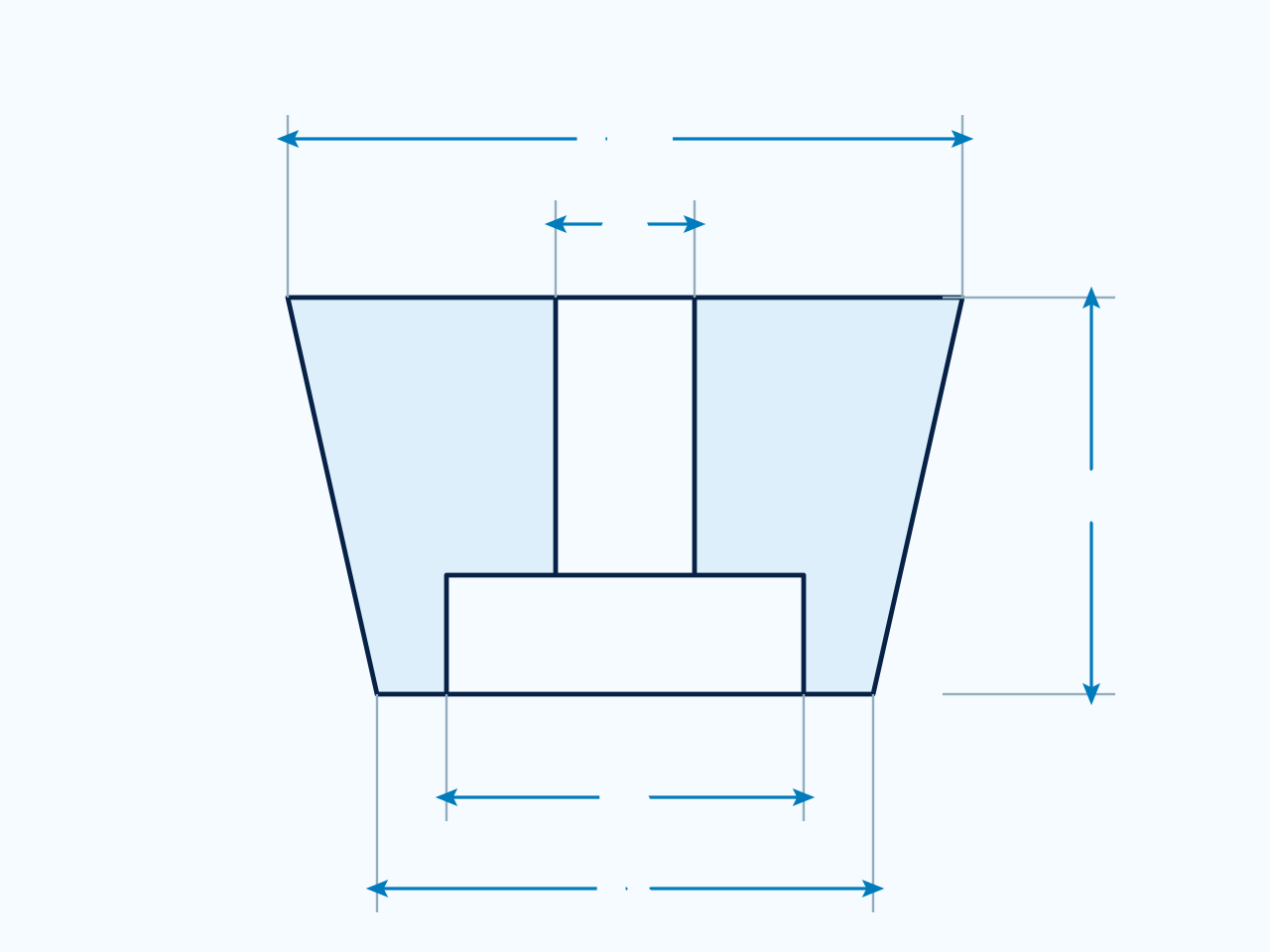
Recess Rubber Bumper
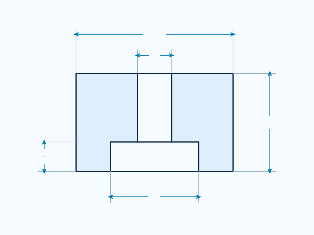
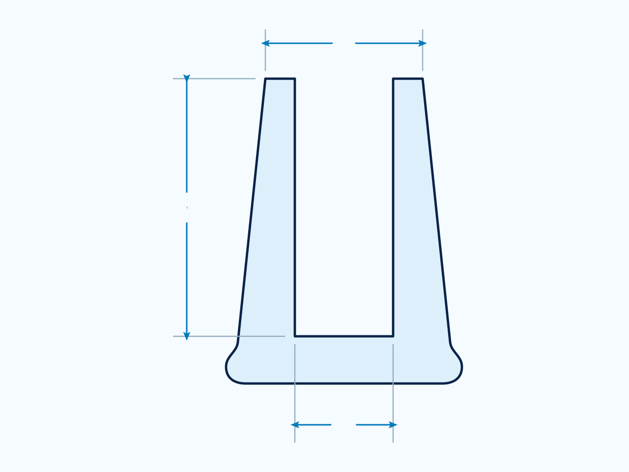
Compare OD, H, A, B and C in mm. C indicates the outer base dimension on this bumper profile, not the recess depth.
Dimension guide
Profile reference. Use the dimension letters and units in the selected table and confirm the part drawing.
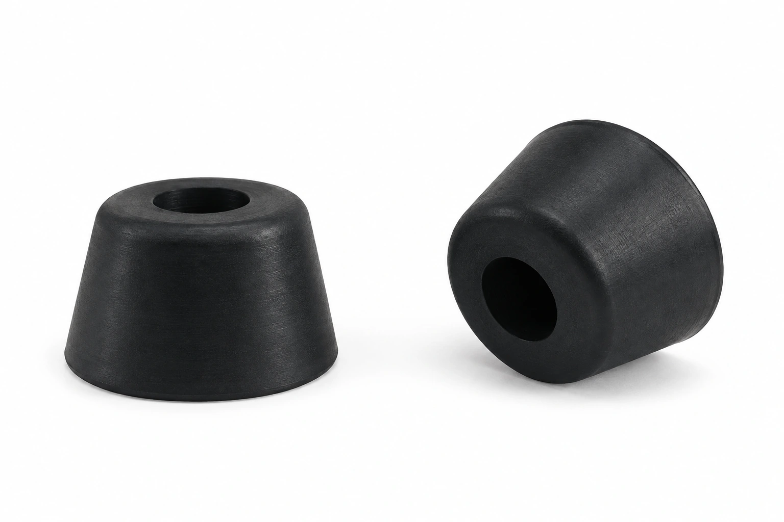
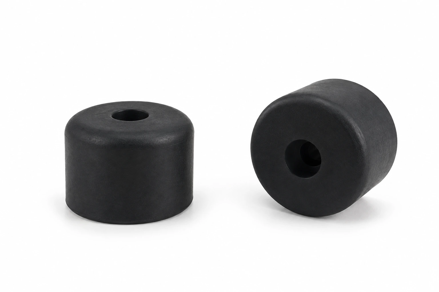
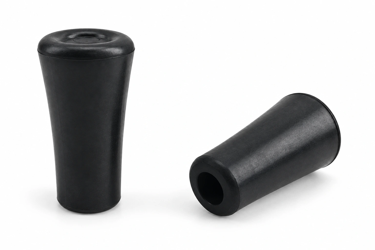
Product appearance
Illustrative product appearance. Refer to the selected row and part drawing for dimensions.
Part No.
OD
H
A
B
C
Material
Color
RBA1001
10.5
4
3
6
9
EPDM/NR
Black
RBA1002
11
6
3
6
9
EPDM/NR
Black
RBA1003
12
7
3
6
5.4
EPDM/NR/Silicone
Black/White/Gray
RBA1004
12
7
3
6
8
EPDM/NR
Black
RBA1005
12
9
3
6
8
EPDM/NR
Black
RBA1006
14
9
3
6
11
EPDM/NR
Black
RBA1007
14
11
3
6
11
EPDM/NR
Black
RBA1008
15
7
4
8
13
EPDM/NR
Black
RBA1009
15
8
3
6
12
EPDM/NR
Black
RBA1010
15.88
12.7
3.97
7.94
6.35
EPDM/NR/Silicone
Black/White/Gray
RBA1011
16
12
4
8
12
EPDM/NR
Black
RBA1012
17
14
3
6
13
EPDM/NR
Black
RBA1013
17
10
4
8
14
EPDM/NR
Black
RBA1014
18
5
3
8
15
EPDM/NR
Black
RBA1015
18
8
4
8
15
EPDM/NR
Black
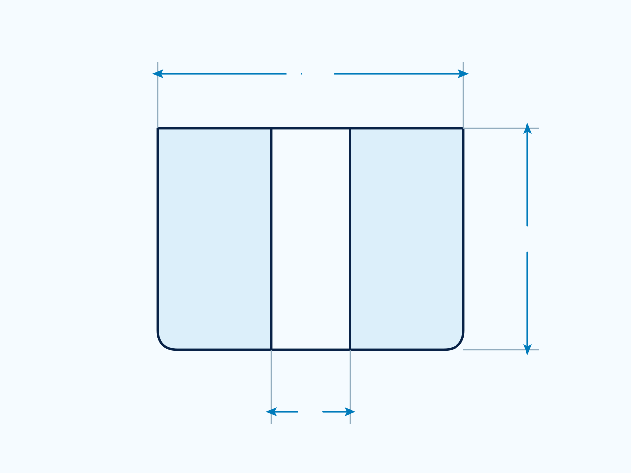
Cylindrical Rubber Feet
Compare OD, H and B in mm using the cylindrical-foot drawing. Material and colour remain listed separately.
Dimension guide
Profile reference. Use the dimension letters and units in the selected table and confirm the part drawing.
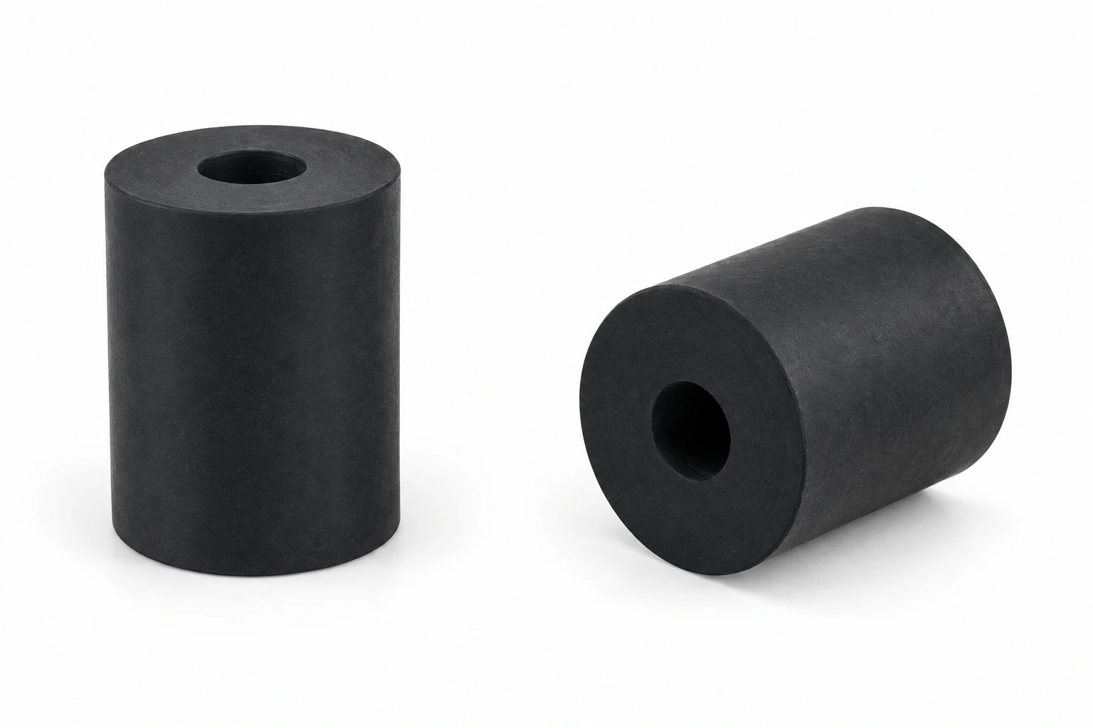
Product appearance
Illustrative product appearance. Refer to the selected row and part drawing for dimensions.
Part No.
OD
H
B
Material
Color
R BC3001
12
6.5
2
EPDM/NR/Silicone
Black/White/Gray
R BC3002
12
6.5
2
EPDM/NR/Silicone
Black/White/Gray
R BC3003
15
6
2
EPDM/NR/Silicone
Black/White/Gray
R BC3004
15
6
2
EPDM/NR/Silicone
Black/White/Gray
R BC3005
18.7
17
2
EPDM/NR/Silicone
Black/White/Gray
R BC3006
20
10
6
EPDM/NR/Silicone
Black/White/Gray
R BC3007
20
10
8
EPDM/NR/Silicone
Black/White/Gray
R BC3008
20
20
10
EPDM/NR/Silicone
Black/White/Gray
R BC3009
20
20
10
EPDM/NR/Silicone
Black/White/Gray
R BC3010
20
10
8
EPDM/NR/Silicone
Black/White/Gray
R BC3011
25
10
8
EPDM/NR/Silicone
Black/White/Gray
R BC3012
25
10
10
EPDM/NR/Silicone
Black/White/Gray
R BC3013
25
10
8
EPDM/NR/Silicone
Black/White/Gray
R BC3014
30
8
10
EPDM/NR/Silicone
Black/White/Gray
R BC3015
30
15
10
EPDM/NR/Silicone
Black/White/Gray
Recess Rubber Feet
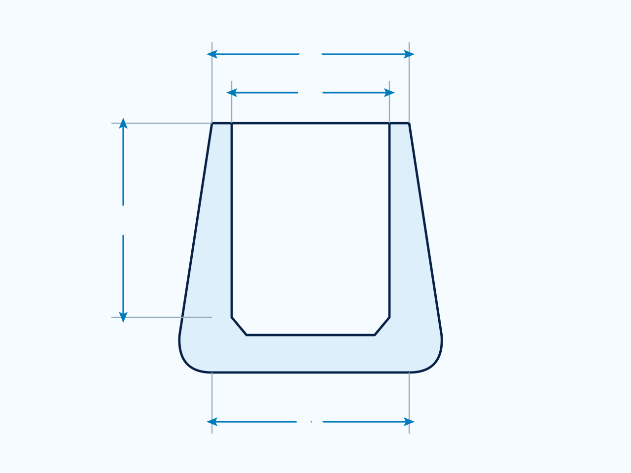
Compare OD, H, A, B and C in mm. C indicates the recess depth on this feet profile.
Dimension guide
Profile reference. Use the dimension letters and units in the selected table and confirm the part drawing.
Product appearance
Illustrative product appearance. Refer to the selected row and part drawing for dimensions.
Part No.
OD
H
A
B
C
Material
Color
RBB2100
12.7
6.35
3.1
6.35
4
EPDM/NR/Silicone
Black/White/Gray
RBB2101
12.7
9.53
3.97
7.94
4
EPDM/NR/Silicone
Black/White/Gray
RBB2102
15
4
3
6
2
EPDM/NR/Silicone
Black/White/Gray
RBB2103
19
7.2
4.8
9.6
3.2
EPDM/NR/Silicone
Black/White/Gray
RBB2104
19
9.5
3.17
9.5
4
EPDM/NR/Silicone
Black/White/Gray
RBB2105
24
11
6
12
6
EPDM/NR/Silicone
Black/White/Gray
RBB2106
26.5
13
4.7
9.5
5
EPDM/NR/Silicone
Black/White/Gray
RBB2107
26.5
21
4.7
9.5
11
EPDM/NR/Silicone
Black/White/Gray
RBB2108
37
15
6
12
8
EPDM/NR/Silicone
Black/White/Gray
RBB2109
38
38
6
19
9.5
EPDM/NR/Silicone
Black/White/Gray
RBB2110
38
38
6.5
19.5
9.5
EPDM/NR/Silicone
Black/White/Gray
RBB2111
41
18
8.3
9.5
6
EPDM/NR/Silicone
Black/White/Gray
Hemispherical Rubber Bumper
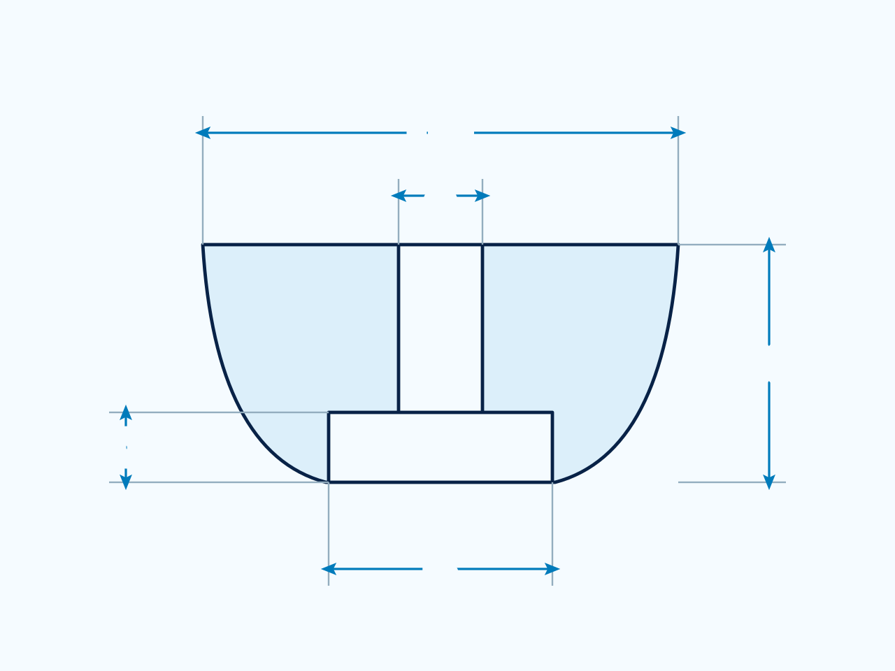
Compare OD, H, A, B and C in mm using the hemispherical-bumper drawing.
Dimension guide
Profile reference. Use the dimension letters and units in the selected table and confirm the part drawing.
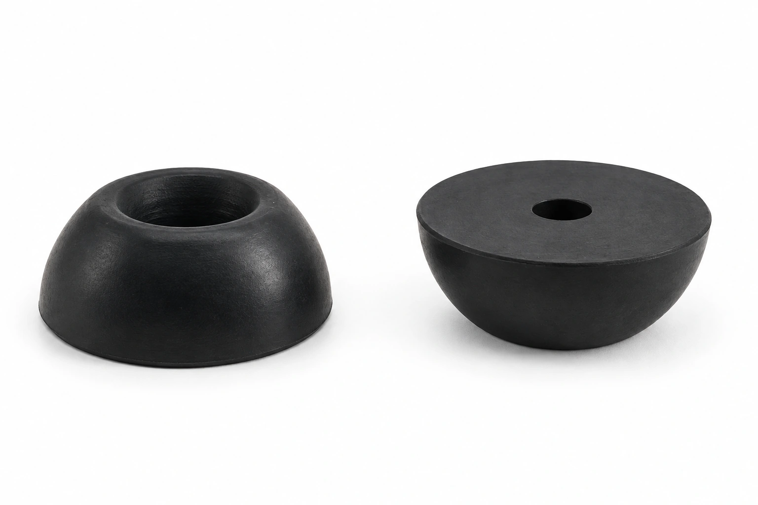
Product appearance
Illustrative product appearance. Refer to the selected row and part drawing for dimensions.
Part No.
OD
H
A
B
C
Material
Color
RBD4101
15
4.5
3.75
6.7
2
EPDM/NR/Silicone
Black/White/Gray
RBD4102
23.7
10
4
7
7
EPDM/NR/Silicone
Black/White/Gray
RBD4103
30
12
8
10
6
EPDM/NR/Silicone
Black/White/Gray
RBD4104
30
16
8
10
10
EPDM/NR/Silicone
Black/White/Gray
RBD4105
41
18
8.3
9.5
6
EPDM/NR/Silicone
Black/White/Gray
Rubber Tips
Compare A, B and C in mm using the open round-tip drawing. Check the mating leg dimensions and seating depth.
Dimension guide
Profile reference. Use the dimension letters and units in the selected table and confirm the part drawing.
Product appearance
Illustrative product appearance. Refer to the selected row and part drawing for dimensions.
Part No.
A
B
C
Material
Color
RFG 7101
14.5
9.5
30
EPDM/NR/SBR/CR/Silicone
According to the Pantone number
RFG 7102
14.5
7.9
32
EPDM/NR/SBR/CR/Silicone
According to the Pantone number
Rectangular rubber feet for chairs
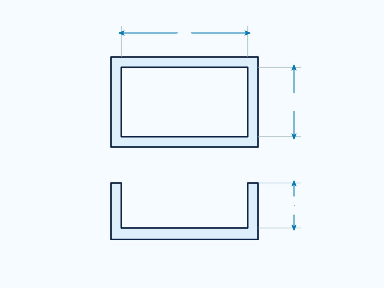
Compare A, B and C in mm using the rectangular-tip drawing. Check both sides of the mating leg and the seating depth.
Dimension guide
Profile reference. Use the dimension letters and units in the selected table and confirm the part drawing.
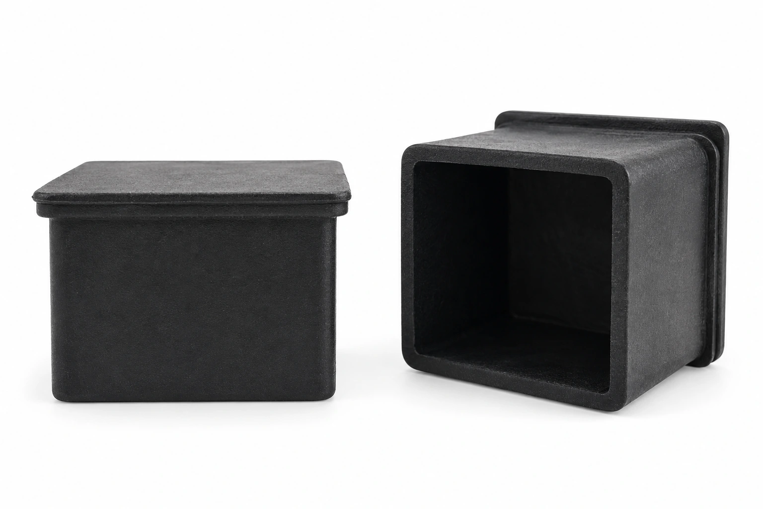
Product appearance
Illustrative product appearance. Refer to the selected row and part drawing for dimensions.
Part No.
A
B
C
Material
Color
RFF6100
15
30
25
PVC
Black
RFF6101
20
20
25
PVC
Black
RFF6102
20
40
26
PVC
Black
RFF6103
25
25
25
PVC
Black
RFF6104
25
50
25
PVC
Black
RFF6105
25
35
25
PVC
Black
RFF6106
30
30
25
PVC
Black
RFF6107
30
40
26
PVC
Black
RFF6108
30
50
28
PVC
Black
RFF6109
38
38
26
PVC
Black
RFF6110
40
40
28
PVC
Black
RFF6111
40
60
28
PVC
Black
RFF6112
50
50
30
PVC
Black
RFF6113
60
60
30
PVC
Black
Rubber Feet For Chairs
Compare A, B, C and D in mm using the square-tip drawing. Check the mating leg profile and seating depth.
Dimension guide
Profile reference. Use the dimension letters and units in the selected table and confirm the part drawing.
Product appearance
Illustrative product appearance. Refer to the selected row and part drawing for dimensions.
Part No.
A
B
C
D
Material
Color
RFE5101
11
6
16
16
EPDM/NR/SBR/CR/Silicone
Black/White/Gray
RFE5102
16.6
12.6
19.6
16
EPDM/NR/SBR/CR/Silicone
Black/White/Gray
RFE5103
18.8
14.7
25.7
18
EPDM/NR/SBR/CR/Silicone
Black/White/Gray
RFE5104
22.1
18.5
28.1
20
EPDM/NR/SBR/CR/Silicone
Black/White/Gray
RFE5105
22.25
17.8
28.55
20
EPDM/NR/SBR/CR/Silicone
Black/White/Gray
RFE5106
24.4
20.8
30.78
20
EPDM/NR/SBR/CR/Silicone
Black/White/Gray
RFE5107
27.51
23.5
33.2
20
EPDM/NR/SBR/CR/Silicone
Black/White/Gray
Need a different size? Share your drawing, mating dimensions and intended use to discuss a suitable part.