
Product Details
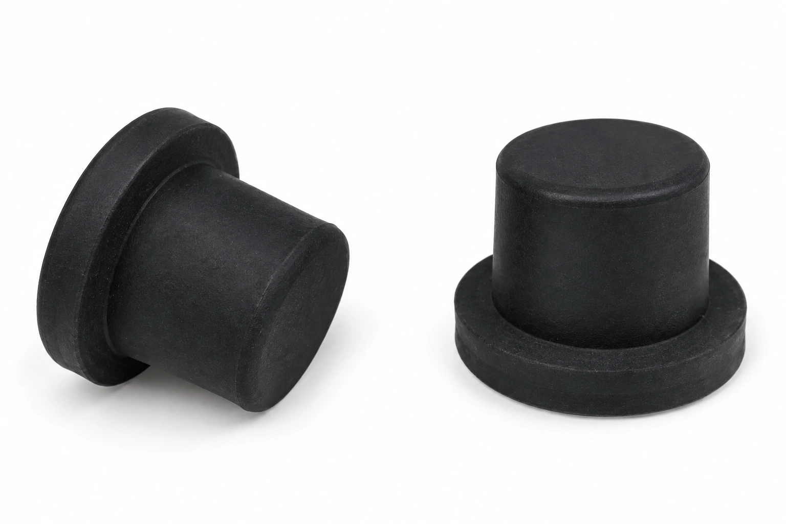
T-Shaped Silicone Stoppers
Product Specifications
- Material
- NR, NBR, EPDM, Silicone, Neoprene, FKM, etc.
- Hardness
- 30-80 Shore A
- Temperature Range
- Confirm the selected compound, service temperature, exposure duration and operating medium before ordering.
- Colors
- Black, white. Custom colors can be matched to your Pantone color code.
Available Sizes
Dimensions are in mm unless otherwise indicated. Custom colors are available to your Pantone color code.
| Part No. | A (mm) | B (mm) | C (mm) | D (mm) | Materials |
|---|---|---|---|---|---|
| RSD2.7-5.5-5 | 2.7 | 5.5 | 5 | 2 | Rubber, Silicone |
| RSD3-7-7 | 3 | 7 | 7 | 2.2 | Rubber, Silicone |
| RSD3.3-6.5-6 | 3.3 | 6.5 | 6 | 1.5 | Rubber, Silicone |
| RSD3.5-6.5-6 | 3.5 | 6.5 | 6 | 2 | Rubber, Silicone |
| RSD3.8-7-6 | 3.8 | 7 | 6 | 1.5 | Rubber, Silicone |
| RSD4-9.5-7 | 4 | 9.5 | 7 | 2.5 | Rubber, Silicone |
| RSD4.3-8-6 | 4.3 | 8 | 6 | 1.5 | Rubber, Silicone |
| RSD4.5-7.5-6 | 4.5 | 7.5 | 6 | 2 | Rubber, Silicone |
| RSD4.8-9-7 | 4.8 | 9 | 7 | 1.5 | Rubber, Silicone |
| RSD5-12-8 | 5 | 12 | 8 | 2.8 | Rubber, Silicone |
| RSD5.3-9.5-7 | 5.3 | 9.5 | 7 | 1.5 | Rubber, Silicone |
| RSD5.5-8.5-7 | 5.5 | 8.5 | 7 | 2 | Rubber, Silicone |
| RSD5.8-10-8 | 5.8 | 10 | 8 | 2 | Rubber, Silicone |
| RSD6-13-8 | 6 | 13 | 8 | 3.5 | Rubber, Silicone |
| RSD6.3-10.5-8 | 6.3 | 10.5 | 8 | 2 | Rubber, Silicone |
| RSD6.5-9.5-7 | 6.5 | 9.5 | 7 | 2 | Rubber, Silicone |
| RSD7-14-9 | 7 | 14 | 9 | 3.5 | Rubber, Silicone |
| RSD7.5-10.5-8 | 7.5 | 10.5 | 8 | 2 | Rubber, Silicone |
| RSD8-15-9 | 8 | 15 | 9 | 3.5 | Rubber, Silicone |
| RSD8.5-11.5-8 | 8.5 | 11.5 | 8 | 2 | Rubber, Silicone |
| RSD9-16-9 | 9 | 16 | 9 | 3.5 | Rubber, Silicone |
| RSD9.5-12.5-8 | 9.5 | 12.5 | 8 | 2 | Rubber, Silicone |
| RSD10-18-10 | 10 | 18 | 10 | 4 | Rubber, Silicone |
| RSD10.5-13.5-9 | 10.5 | 13.5 | 9 | 2 | Rubber, Silicone |
| RSD11-19-10 | 11 | 19 | 10 | 4 | Rubber, Silicone |
| RSD11.5-14.5-9 | 11.5 | 14.5 | 9 | 2 | Rubber, Silicone |
| RSD12-20-10 | 12 | 20 | 10 | 4 | Rubber, Silicone |
| RSD12.5-15.5-10 | 12.5 | 15.5 | 10 | 2 | Rubber, Silicone |
| RSD13-21-10 | 13 | 21 | 10 | 4 | Rubber, Silicone |
| RSD13.5-16.5-10 | 13.5 | 16.5 | 10 | 2 | Rubber, Silicone |
Can’t find your size? Need a custom part?
Contact us with your dimensions, drawing or sample requirements. We’ll help you review a custom size, shape or material for your application.
MEASURE · SELECT · INSTALL
Find the right fit for your opening
Start with the hole, compare the dimensions above, then confirm the fit with a sample in your actual assembly.
01 / MEASURE
Read the drawing. Measure the hole.
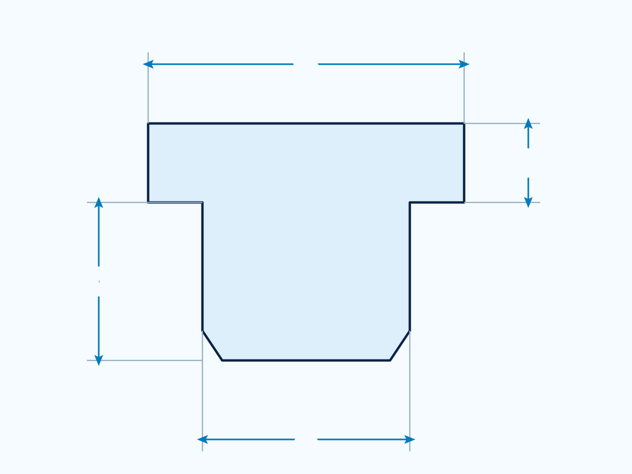
The letters below refer to this T-shaped stopper’s drawing and size table. All dimensions are in mm.
- A Stem diameter
- Across the straight body below the flange, above the chamfered tip. Compare with the measured hole diameter.
- B Flange diameter
- Across the widest part of the head. Check the flat seating area and clearance to nearby parts.
- C Stem length
- From the underside of the flange to the tip. Check the available depth below the seating surface.
- D Flange thickness
- From the top of the head to its underside. Allow room above the surface; overall part height is C + D.
- Measure the bore, not just the opening. Use inside caliper jaws or a suitable bore gauge. Measure in two directions and at the intended contact depth; record the smallest and largest readings. Note any chamfer, thread or taper.
- Measure depth from the seating surface. For a blind hole, record the distance to the bottom and any obstruction. For a through-hole, record panel thickness and the free space behind it.
- Record the surrounding space. Check room for flange B, head thickness D and access for removal. Send units, hole tolerances and whether dimensions are measured or nominal.
A is the stopper diameter, not a specified hole size. Do not assume A equals the hole diameter or apply a universal oversize allowance. Fit depends on the selected dimensions, material and hardness; confirm the allowance and sample fit before ordering.
02 / SELECT
Compare three stopper structures
Choose how the part seats and stays in place, then use the drawing for that series. Dimension letters are not interchangeable between series.
T-shaped
A wide flange rests on the face; the straight stem fits inside the bore. This page shows the solid T-shaped version.
Check: stem fit, flange space and available insertion depth. The flange sets the seating position; it does not lock behind the panel.
View this size tableTapered / RSA
The body narrows toward the tip. The diameter in contact with the hole changes as the stopper is pushed in.
Check: both end diameters, contact depth and removal access. Do not use the large-end diameter alone to choose a size.
View tapered stoppersUndercut / RSB
A retaining lip sits behind the panel, leaving the panel between the lip and the flange.
Check: hole diameter, panel thickness, groove and rear clearance. The RSB drawing shows an underside recess marked E, beneath a closed head. Check the selected row: some models list E = 0.
View undercut plugsProfiles are schematic and not to scale. Comparing with the RST T-shaped series? Check its separate drawing and the underside recess dimension E in the selected row; the recess is not shown as a through-hole.
03 / INSTALL
Seat the flange. Check the sample.
Inspect the hole for burrs and sharp edges, clean the mating surfaces and align the stem with the bore. Apply even pressure by hand. Stop if the part jams, folds or needs excessive force; recheck the dimensions.
Sample trial checklist
- Seating: the flange rests evenly, with no folded edge or visible damage.
- Depth: the tip clears the blind-hole bottom; for a through-hole, check protrusion and nearby components.
- Retention and removal: check insertion and pull-out force against your assembly requirements. For an undercut plug, confirm the lip fully engages behind the panel.
- Service conditions: test in the intended temperature and medium. If sealing is required, validate leakage at the specified pressure or vacuum; a seated plug alone does not establish a sealing rating.
Using an undercut instead?
The lip must pass through the hole and sit behind the panel. Confirm the panel fits the retaining groove and leaves enough rear space for the lip to engage. Verify from the rear where accessible.
For a fit review: send the part number, measured hole diameter and tolerance, hole depth or panel thickness, available space, material requirements and trial observations. Include these in your inquiry.
Need a different size or shape?
Tell us what you need. We'll help you find the right rubber or silicone part and prepare a quote.