
Product Details
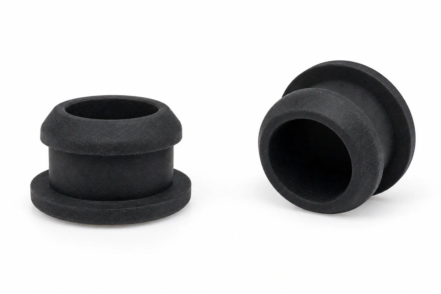
Silicone Plugs(Undercut-RSB)
Product Specifications
- Material
- Silicone,NR, NBR, EPDM, Neoprene, FKM, etc.
- Hardness
- 20-75 Shore A
- Temperature Range
- Confirm the selected compound, service temperature, exposure duration and operating medium before ordering.
- Colors
- Black, white. Custom colors can be matched to your Pantone color code.
Available Sizes
Dimensions are in mm unless otherwise indicated. Custom colors are available to your Pantone color code.
| Part No. | A (mm) | B (mm) | C (mm) | D (mm) | E (mm) |
|---|---|---|---|---|---|
| RSB2.5-6-3 | 2.5 | 6 | 3 | 1.5 | 0 |
| RSB3-7-3 | 3 | 7 | 3 | 2 | 0 |
| RSB3.5-7.5-3 | 3.5 | 7.5 | 3 | 2 | 0 |
| RSB3.6-7.5-6 | 3.6 | 7.5 | 6 | 2 | 0 |
| RSB4-8-3 | 4 | 8 | 3 | 2 | 0 |
| RSB4.5-8.5-3 | 4.5 | 8.5 | 3 | 2 | 2 |
| RSB5-9-3 | 5 | 9 | 3 | 2 | 2.5 |
| RSB5.5-9.5-3 | 5.5 | 9.5 | 3 | 2 | 3 |
| RSB6-10-4 | 6 | 10 | 4 | 2 | 3.5 |
| RSB6.5-10.5-4 | 6.5 | 10.5 | 4 | 2 | 4 |
| RSB6.5-12-8 | 6.5 | 12 | 8 | 2 | 0 |
| RSB6.7-8.7-5.3 | 6.7 | 8.7 | 5.3 | 1.3 | 4.1 |
| RSB7-11-4 | 7 | 11 | 4 | 2 | 4.5 |
| RSB7.5-11.5-4 | 7.5 | 11.5 | 4 | 2 | 5 |
| RSB8-12-4 | 8 | 12 | 4 | 2 | 5.5 |
| RSB8-12-5 | 8 | 12 | 5 | 3.5 | 5.5 |
| RSB8.5-12.5-4 | 8.5 | 12.5 | 4 | 2 | 6 |
| RSB8.7-10.7-5.8 | 8.7 | 10.7 | 5.8 | 2 | 6.1 |
| RSB9-13-5 | 9 | 13 | 5 | 2 | 6.2 |
| RSB9.5-13.5-5 | 9.5 | 13.5 | 5 | 2 | 6.5 |
| RSB10-14-5 | 10 | 14 | 5 | 2 | 7 |
| RSB10.5-14.5-5 | 10.5 | 14.5 | 5 | 2 | 7.5 |
| RSB11-15-5 | 11 | 15 | 5 | 2 | 8 |
| RSB11.5-15.5-5 | 11.5 | 15.5 | 5 | 2 | 8.5 |
| RSB12-16-5 | 12 | 16 | 5 | 2 | 9 |
| RSB12-15.9-6.5 | 12 | 15.9 | 6.5 | 1.9 | 0 |
| RSB12.5-16.5-5 | 12.5 | 16.5 | 5 | 2 | 9.5 |
| RSB13-17-5 | 13 | 17 | 5 | 2 | 10 |
| RSB13.5-17.5-6 | 13.5 | 17.5 | 6 | 2.5 | 10.3 |
| RSB13.5-18-7 | 13.5 | 18 | 7 | 3 | 10 |
| RSB14-18-6 | 14 | 18 | 6 | 2.5 | 10.5 |
| RSB15-19-6 | 15 | 19 | 6 | 2.5 | 11 |
| RSB16-20-6 | 16 | 20 | 6 | 2.5 | 12 |
| RSB17-21-6 | 17 | 21 | 6 | 2.5 | 13 |
| RSB17.5-25-7.3 | 17.5 | 25 | 7.3 | 3 | 14 |
| RSB18-23-7 | 18 | 23 | 7 | 3 | 14 |
| RSB19-24-7 | 19 | 24 | 7 | 3 | 15 |
| RSB20-25-7 | 20 | 25 | 7 | 3 | 16 |
| RSB21-26-7 | 21 | 26 | 7 | 3 | 16.5 |
| RSB22-27-7 | 22 | 27 | 7 | 3 | 17.5 |
| RSB22-30-5.5 | 22 | 30 | 5.5 | 3 | 17 |
| RSB23-28-7 | 23 | 28 | 7 | 3 | 18.5 |
| RSB24-29-7 | 24 | 29 | 7 | 3 | 19 |
| RSB25-31-8 | 25 | 31 | 8 | 3.5 | 20 |
| RSB26-32-8 | 26 | 32 | 8 | 3.5 | 21 |
| RSB27-33-8 | 27 | 33 | 8 | 3.5 | 22 |
| RSB27-35-4.5 | 27 | 35 | 4.5 | 3 | 22 |
| RSB28-34-8 | 28 | 34 | 8 | 3.5 | 23 |
| RSB29-35-8 | 29 | 35 | 8 | 3.5 | 24 |
| RSB30-36-8 | 30 | 36 | 8 | 3.5 | 25 |
Can’t find your size? Need a custom part?
Contact us with your dimensions, drawing or sample requirements. We’ll help you review a custom size, shape or material for your application.
MEASURE · SELECT · INSTALL
Match the undercut to the panel
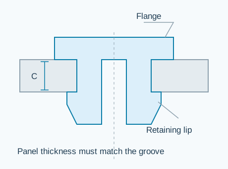
RSB adds a retaining lip below the flange. The panel must fit between those features, with space behind it for the lip to pass through and recover.
01 / MEASURE
Measure panel thickness as well as the hole
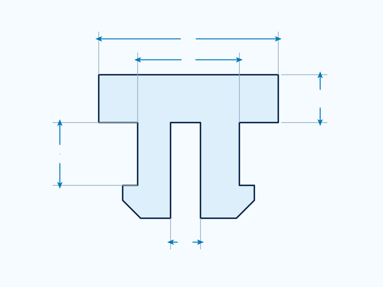
Use these definitions with this page’s drawing and model table. Dimensions are in mm; letters may describe different features in other series.
- ANeck diameter
- Across the section that sits in the panel hole, above the retaining lip. It is not the maximum diameter of the lip.
- BFlange diameter
- Across the head. Check the available seating surface around the hole.
- CFlange-to-lip distance
- From the flange underside to the upper shoulder of the retaining lip. Compare with finished panel thickness; C does not include the lower lip and tip.
- DFlange thickness
- The height above the panel face. C + D is not the total height of this undercut profile.
- EUnderside recess diameter
- A recess is shown below a closed head. The table contains E = 0 and nonzero variants. Confirm the exact recess and lip profile for the chosen model.
- Measure the finished hole. Record diameter, tolerance, edge radius or chamfer and any coating. Include sheet layers or a formed collar around the opening.
- Measure the full panel stack. Record the thickness that must sit between the flange and lip. Do not assume that matching A alone guarantees retention.
- Check rear clearance. Identify space for the lip to pass through and seat. Ask for the lip outside diameter and overall length if these are needed; the A–E table does not separately list them.
02 / SELECT
Choose a lip when the rear face can engage it
Panel-hole retention
Consider the undercut when the plug must be captured behind a panel. Confirm panel thickness, lip engagement and the required pull-out behavior together.
Thick walls or blind bores
If the lip cannot reach a rear face, this retention arrangement cannot be assumed. Review a straight T-shaped or tapered profile for the available geometry.
03 / INSTALL
Confirm that the lip clears the rear face
Trial assembly checks
- Inspect the edge. Remove loose debris and check for burrs. Align the plug so the lip enters the hole evenly.
- Check full engagement. Press the plug into place and inspect the rear where accessible. The lip must be beyond the panel, not trapped or folded inside the hole.
- Check axial play and retention. Confirm the head sits as intended and the panel is captured. Compare looseness and pull-out force with the agreed requirements.
- Plan removal access. Confirm how the plug can be released without tearing the lip or damaging the panel. Trial the expected number of installation and removal cycles.
Send for a fit review: RSB part number, hole diameter and tolerance, finished panel thickness, rear clearance, edge detail, retention requirement and removal access. Add these details to your inquiry.
Need a different size or shape?
Tell us what you need. We'll help you find the right rubber or silicone part and prepare a quote.